RAF Barnham was home of the 94th Maintenance Unit, this was where the payload of the UKs first Nuclear Deterrent the “Blue Danube” was maintained. The payload had a very short half-life so every few weeks returned here via truck from the southern V-Bomber sites for maintenance.
There was a sister site at RAF Faldingworth that maintained the northern airfields but this is the only complete example remaining more information can be found here https://rafbarnham-nss.weebly.com/
In 2022 with permission from the site owners we took a couple of hundred 360 photos, I’ve used a small selection to create a virtual tour of this amazing location, please enjoy.
Click below for the virtual tour:
https://tour.panoee.com/barnham360
PunKtuation are back
Remember PunKtuation the Herts based punkpop band from 20 years ago?
we are back check out https://punktuation.iamanerd.org.uk if you care!
Vox Escort lead 50W combo
A while back I bought this Vox escort lead amplifier, its a 50W model with a blue labelled vox VSL limited speaker and PCB manufactured by the Faraday group of companies.
The PCB says bass 30-50 yet is not a bass amp.
I’m trying to date it and get the Schematic, any information would be greatly recieved!
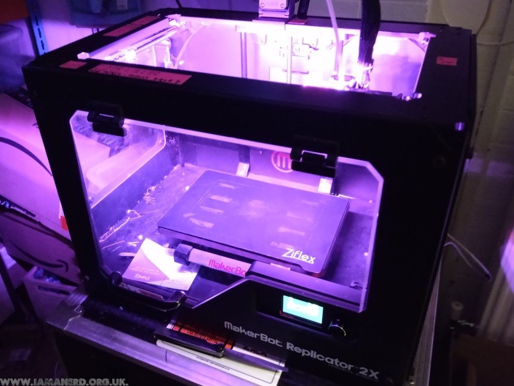
Makerbot Replicator 2X BTT SKR 1.4 Turbo
THIS POST IS A WORK IN PROGRESS
Last year I swapped the original mightyboard and botstep drivers from my replicator 2x over to a modern 32 bit board the bigtreetech SKR 1.4 turbo with 2.4″ TFT and converted it to a bowden setup.
Several people asked how so I’m going to attempt to write it it up. I will continue to add to this as I get time.
This is the basic process you need to follow if you want to do it like I have:
– remove mightyboard c/w Botsteps
– remove LCD and mount
– remove original stepper motor wiring and replaced with generic ones.
– cut connectors off the endstops and re-crimp JST connectors on instead.
– fit 24vdc PSU under the bed
– fit BTT SKR in place of mightyboard with 5 x drivers (I used TMC2208s in standalone mode)
– add TFT24 mount and LCD
– add extract fan to base
– add thermistor to bed in place of the Makerbot one.
– cut remaining connectors and changed to JST.
– swap the the thermocouples for M3 thermistors (alternatively you can buy a thermocouple board for the SKR)
– add mosfet for hotend fan control
– edit and compile marlin firmware.
Optional steps I undertook:
– Converted to Bowden setup by changing the extruders for E3D Titan extruders and the Hotends for an E3D V6 Chimera hotend.
– changed the LED strip over to NeoPixel.
– made new lid.
Parts list:
– JST Connector kit and Crimp tool.
– 4 x 1m and 1 x 0.25M HX2.54 NEMA stepper cables (4 pin to 6 pin).
– 24vdc switchmode Power Supply.
– BTT TFT24.
– BTT SKR 1.4 Turbo c/w 5 x drivers (I used TMC2208s in standalone mode)
– Some wires.
– Assorted heatshrink.
– Clear acrylic for Lid.
– Some more wires.
Printed Parts I designed:
– BTT TFT24 Mount for replicator 2X https://www.thingiverse.com/thing:4552223
– Mightyboard rev h SKR 1.4 adapter https://www.thingiverse.com/thing:4700179
– BLtouch mount https://www.thingiverse.com/thing:4258034
– E3D Titan Mount for Replicator 2X https://www.thingiverse.com/thing:4463398
– E3D Chimera Mount for Replicator 2X https://www.thingiverse.com/thing:4699838
– Lid cover parts https://www.thingiverse.com/thing:4463425
– Octoprint Pi Bracket (Not finished)
I would recommend that you have the following tools handy:
– Soldering iron & Solder
– wire cutters
– JST Crimpers
– Screwdrivers
– Allen keys
JST Connectors and crimping:
You will use allot of JST connectors if using the SKR turbo, it is really important that you practice crimping these and ensure you crimp the connectors well, I’m using a cheap ratchet crimper and its pretty rubbish but with practice I’ve managed to crimp the cables pretty well with them.
My conversion process explained:
First job is one of the easiest parts of the process, remove all connectors from the the Mightyboard then pull it c/w Botsteps from the standoffs in the base, remove the front door and front panel then remove the LCD and mount.
Now you can remove the original stepper motor looms and replace them with generic ones, I used 4 x 1m and 1 x 0.25M for the Z motor.
At this point you can mount your PSU if you are using an internal one, I chose to screw mine through the base under the bed with 4 X M3 screws.
You can also mount the BTT TFT24 in the printed case now, this screws into the original mounting holes. Be sure to get the EXT connectors and the 5 pin one in the right order, I cut the black wires and crimped a JST connector on the smaller one to ensure that it couldn’t be reversed.
I mounted the BTT main board using standoffs drilled through the bed base but I have subsequently designed an adaptor that you can screw the BTT onto which then clips onto the original standoffs.
Once the new motherboard and TFT is mounted you can finish the wiring, you’ll need to cut the connectors off the Endstops and from the bottom of the extruder/hotend looms.
The Hotend heater cables can be wired directly into the board however the BTT SKR cannot read thermocouples without an additional board so I would swap them for M3 thermistors, you’ll need to crimp JSTs on the thermistor cables (Don’t worry about the polarity).
For the endstops you only need one ground as these are joined on the PCB so just connect the 5v to VCC, Gnd to Gnd and sig to the signal pin.
As the BTT SKR Turbo can only control one fan, I added a Mosfet for the extruder fans (covered in another post here) I also added an extract fan to the base to pull warm air away from the motherboard and PSU paralleled to the output of the mosfet.
I found once completed that the bed thermistor read very low, I think this is because of its placement within the silicone heat mat.
I added a new 100K thermistor in the heat bed with a bit of thermal compound and aluminium tape to hold it onto the back of the bed surface, this now reads very accurately.
Firmware:
Firstly I am not going to upload my complete firmware as its irrelevant unless you have literally the same setup as me plus If you can’t handle editing code and compiling it you shouldn’t be doing this conversion.
Marlin isn’t complicated and I’m not going into how to compile it but I will help with some useful snippets from mine.
Configuration.h
//Original Hotend Offsets
// Offset of the extruders (uncomment if using more than one and relying on firmware to position when changing).
// The offset has to be X=0, Y=0 for the extruder 0 hotend (default extruder).
// For the other hotends it is their distance from the extruder 0 hotend.
#define HOTEND_OFFSET_X { 0.0, 34.6 } // (mm) relative X-offset for each nozzle
#define HOTEND_OFFSET_Y { 0.0, 0.00 } // (mm) relative Y-offset for each nozzle
#define HOTEND_OFFSET_Z { 0.0, 0.00 } // (mm) relative Z-offset for each nozzle
//===========================================================================
//============================== Endstop Settings ===========================
//===========================================================================
// @section homing
// Specify here all the endstop connectors that are connected to any endstop or probe.
// Almost all printers will be using one per axis. Probes will use one or more of the
// extra connectors. Leave undefined any used for non-endstop and non-probe purposes.
//#define USE_XMIN_PLUG
#define USE_YMAX_PLUG
#define USE_ZMIN_PLUG
#define USE_XMAX_PLUG
//#define USE_YMAX_PLUG
//#define USE_ZMAX_PLUG
// Enable pullup for all endstops to prevent a floating state
#define ENDSTOPPULLUPS
#if DISABLED(ENDSTOPPULLUPS)
// Disable ENDSTOPPULLUPS to set pullups individually
//#define ENDSTOPPULLUP_XMAX
//#define ENDSTOPPULLUP_YMAX
//#define ENDSTOPPULLUP_ZMAX
//#define ENDSTOPPULLUP_XMIN
//#define ENDSTOPPULLUP_YMIN
//#define ENDSTOPPULLUP_ZMIN
#define ENDSTOPPULLUP_ZMIN_PROBE
#endif
// Enable pulldown for all endstops to prevent a floating state
//#define ENDSTOPPULLDOWNS
#if DISABLED(ENDSTOPPULLDOWNS)
// Disable ENDSTOPPULLDOWNS to set pulldowns individually
//#define ENDSTOPPULLDOWN_XMAX
//#define ENDSTOPPULLDOWN_YMAX
//#define ENDSTOPPULLDOWN_ZMAX
//#define ENDSTOPPULLDOWN_XMIN
//#define ENDSTOPPULLDOWN_YMIN
//#define ENDSTOPPULLDOWN_ZMIN
//#define ENDSTOPPULLDOWN_ZMIN_PROBE
#endif
// Mechanical endstop with COM to ground and NC to Signal uses "false" here (most common setup).
#define X_MIN_ENDSTOP_INVERTING true // Set to true to invert the logic of the endstop.
#define Y_MIN_ENDSTOP_INVERTING true // Set to true to invert the logic of the endstop.
#define Z_MIN_ENDSTOP_INVERTING true // Set to true to invert the logic of the endstop.
#define X_MAX_ENDSTOP_INVERTING true // Set to true to invert the logic of the endstop.
#define Y_MAX_ENDSTOP_INVERTING true // Set to true to invert the logic of the endstop.
#define Z_MAX_ENDSTOP_INVERTING true // Set to true to invert the logic of the endstop.
#define Z_MIN_PROBE_ENDSTOP_INVERTING true // Set to true to invert the logic of the probe.
// @section machine
// Invert the stepper direction. Change (or reverse the motor connector) if an axis goes the wrong way.
#define INVERT_X_DIR true
#define INVERT_Y_DIR true
#define INVERT_Z_DIR true
// @section homing
// Direction of endstops when homing; 1=MAX, -1=MIN
// :[-1,1]
#define X_HOME_DIR 1
#define Y_HOME_DIR 1
#define Z_HOME_DIR -1
// @section machine
// The size of the print bed
#define X_BED_SIZE 235
#define Y_BED_SIZE 150
// Travel limits (mm) after homing, corresponding to endstop positions.
#define X_MIN_POS 0
#define Y_MIN_POS 0
#define Z_MIN_POS 0
#define X_MAX_POS 235
#define Y_MAX_POS 150
#define Z_MAX_POS 150
Configuration_adv.h
#define E0_AUTO_FAN_PIN P1_00
That is kind of it for the basics, I’ll try to add any more information as I think of it but there should be enough here to get you through a conversion, I’ll try and write up my bowden conversion soon.
Have fun.
Still to write up:
– make new lid https://www.thingiverse.com/thing:4463425
– changed the extruders for E3D Titan extruders https://www.thingiverse.com/thing:4463398
– changed the Hotends for E3D V6 Chimera hotend https://www.thingiverse.com/thing:4699838
– changed the LED strip over to NeoPixel
Adding an additional fan on BTT SKR 1.4 Turbo using Marlin
When I built my Replicator 2X using a BTT SKR 1.4 Turbo I was disappointed to learn that only one of the three fans is controllable.
I really wanted an automatic extruder fan and with an external MOSFET it’s a really simple thing to setup.
All you need to do is connect a MOSFET to a spare pin (I chose the power detect plug).
Using a DFRobot GRAVITY MOSFET (other brands are available) I connected the red to 5v, black to GND and green to pin 1.00
I connected the fan to the output of the mosfet using the output from fan1 for the VIN but you could obviously use your PSU aswell (Make sure this is the correct voltage for the fan!!)
In configuration.adv I changed the extruder fan pin to “P1_00” from “-1” compiled Marlin, uploaded it and bingo!
Automatic fan on extruder 1!
Really simple and well worth it!
RWD Automatic Zetec conversion.
Here I will document my Automatic RWD Zetec conversion it is not a guide nor advice, just a record of how I converted a FWD zetec engine to a RWD Automatic with a few extras I learnt along the way thrown in.
Engine:
I’m using a 2.0 blacktop zetec from a 1999 Mondeo with a Ford focus EFI and ECU from 2001 and a Ford C3 Automatic Transmission from a 1975 2.3 Mustang.
To RWD convert this it has a Sierra sump and oil pickup fitted.
I’ve opted for the retro ford alternator kit and will be using their DIY mount kit aswell.
As space isn’t an issue in my application I’m using the original thermostat housing so no need for a water rail.
Transmission:
I’m using a Ford C3 Automatic Transmission originally from a 2.3 Mustang with a Mondeo automatic flexplate (135 tooth, 11.3″) and Mondeo automatic crank sensor. The A4LD box was also an option but I wanted the simplicity of the C3 transmission.
I had a local engineering firm drill the TC mounting holes in the flexplate using a lathe to get them spot on.
There are at least 3 bellhousings for the C3 box which will fit on the zetec and all these need the smaller 3 bolt torque converter as the 4 bolt version fouls on the zetec timing gear.
2.3 Mustang bellhousing bolts straight up to the zetec but requires the correct Mustang starter (1974-1985) or an adapter for the sierra starter and the smaller British TC.
1.6 Crossflow bellhousing (Escort etc) this bellhousing requires the smaller TC and a Sierra DOHC starter but as it’s considerably deeper than the pinto one you will also need a spacer between the TC and flexplate (approx 10mm), the starter is on the opposite side to the others.
2.0 Pinto bellhousing (Cortina etc)
Although I’ve not tested this myself I’m told it’s the same depth as the Mustang one so should bolt straight up using the smaller TC and the sierra DOHC starter.
When originally fitting the Torque Converter I didn’t have it seated properly, A tip given to me was to smear a line of grease on the rear end of the TC that way you can ensure its fully located as after removal you can see how far the rear seal came up the TC!
The Automatic flexplate bolts are different to the manual flywheel ones and have been discontinued by ford, luckily retro ford had some in stock. They are a class 10.9, M11 X 1.0 pitch bolt, the thread is 15mm long with a 2mm shank, they have an 18mm hex head which is 6mm tall.
Starter motor spacer:
Whatever the transmission you’ll need to space your starter so it engages and disengages properly with the Mondeo flexplate.
With a sierra starter I found a 10mm spacer was needed and the same with the Mustang however I made an adapter plate so I could fit a sierra starter on instead of the OG Mustang one.
The flexplate teeth sit approximately 8-18mm from the sandwich plate.
Hopefully this helps someone and I’ll try and finish the write up at some point.
Thankyou Neil for all your help and encouragement along the way.
Press to continue…
Press to Continue were a Ska punk band from North Hertfordshire, originally comprising of four members Tim with his voice, Joe on bass, Ryan hitting drums and Tom playing guitar. They were later joined by Amie on vocals and Luke on sax with a brief stint from drummer Jordan.
Their last gig was in 2009 and some of their music is still available here https://www.soundclick.com/bands3/default.cfm?bandID=857541
Econoline throttle cable adapter bracket
I wanted to replace the accelerator rod setup on my 64 Econoline with a cable one so I built this very simple adapter to use the existing pedal assembly, since these photos I have changed the washer and spring setup to look a little neater but it works incredibly well.
I fitted a pair of Rivnuts to the front valence and bolted the bracket to them, the original pedal arm on the assembly rests on the bracket and I used a bolt to attach the cable end and spring to the original assembly arm.
This is the bracket, its very simple but effective!
Fitted bracket:
D&D disk brake conversion and master cylinder upgrade kits – My experience with them.
This post is about my personal experience with fitting the D&D brake and master cylinder conversion kits on an early ford Econoline, it is not a guide and I take no responsibility for anything you learn here. I fitted this with a mate and couldn’t have done it alone.
Overall I am very pleased with the kits, my van now stops straight and perfectly everytime I feel so much safer driving it however the instructions are somewhat lacking and miss a few key points.
General Notes:
I chose to powder coat my brackets, they are well made items but unpainted and personally I don’t want mine rusting away under the van.
DO NOT USE A PRESS for any of the installation, it isn’t needed and will do more damage than good.
Disk conversion kit:
1. If you press the studs out of the drums you risk destroying the hubs, so remove the drums you will need to cut the “Swage” from around the studs, to do this I used a bench drill with a 5/8″ hole cutter and the pilot drill removed, I ran the stud inside the hole saw and it cut the studs out perfectly. But make sure you don’t go too far as you will either damage the hubs or shatter the hole saw.
Once these are drilled out tap the hub from the drum with a hammer.
2. It is imperative that the holes in the Jeep disks are 5/8″ unfortunately due to manufacturing tollerances this cannot be assumed so ream or drill out these holes to 5/8″ (16mm) mine were close but not all uniformed. The kit would not assemble correctly without drilling these out.
3. Do not press the new studs in, tap them in with a hammer, in fact you don’t need a press for this kit at all! If you press them in you risk damaging the hubs and shattering the new disks.
I would suggest laying a wheel on the bench, assembling the components (studs, disks and hubs) tapping the studs through and tightening them up with wheel nuts, this will make sure that the whole lot goes together true.
4. While you have your van in the air and in pieces clean your suspension components and grease your kingpins, it will significantly improve the ride.
5. The recommended brake hoses do not fit they are too short, we simply relocated the the brackets to the chassis and welded them in however I am told that the 4WD S10 Blazer flexi’s are longer and may work.
The completed disk conversion with relocated flexi hose bracket:
Master cylinder kit:
1. With the supplied cylinder the larger port goes to the rear brakes this at the rear of the vehicle when fitted and the smaller to the front (the one at the pushrod end).
D&D supply a short adapter hose for the rear brakes which we put a proportioning valve on and ran straight to the rears but in theory you don’t need this and could just use a straight coupler.
If I were to do this again though I’d use a T-piece sending one line to the rears and one to a brake pressure switch binning the mechanical switch supplied.
The front outlet comes with an adapter to make it work with a standard inverted flare 3/8 fitting which I ran to a T-piece sending one line left and one right.
2. The aluminium turned caps just need pushing into the master cylinder gently until you feel resistance, they don’t need to be pushed all the way in as it’s a low pressure feed, try to source angled hose barbs for these. I cut down straight ones.
3. I fitted my resorvoir in the cab, I drilled a couple of holes in the cab floor and ran the hoses up to a resorvoir behind the front panel.
You need brake feeder pipe between the reservoir and the master cylinder, do not use fuel hose or anything else it will perish. I bought aircooled vw beetle hoses as they are readily available but summit do sell it.
Make sure there are no kinks or tight bends in the hose so the fluid can fall down to the master cylinder.
4. My pedal free play was massive, I understand there should be around 1mm free play at the master cylinder but even with the eccentric nut this was too much giving a very floppy pedal, We added 5mm to the pushrod by welding a section of M8 bolt shaft in which solved it. Obviously you may not have this issue and if you do you’d need to calculate the correct length yourself.
5. Bleeding, bleeding bloody bleeding! when fitting these kits I replaced everything front and back, shoes, pipes, cylinders, flexi’s the lot which meant lots of air and bleeding was an absolute ass, we ended up backfeeding fluid with a syring into the front lines to get it to start bleeding so I’d suggest following the advice and bench bleeding the MC beforehand.
Completed master cylinder kit:
I hope this post helps someone as this is a great way to add some stopping power to your 1961-67 Econoline.
Raspberry Pi 3 (stretch) and Wirelessthings sensors
After successfully running for 18 months my SD card failed probably due to the amount of mysql data read/writes. Luckily it failed read only so I didn’t loose too much data however I decided to start fresh using rasbian stretch and an external mysql table on a traditional drive (Not an SD Card) so here is a little guide of what I did again it assumes you have no mouse, keyboard or monitor attached and is correct as of December 2017
Prepare the Pi:
1. Download the latest Raspbean Stretch Image and Using your favourite method, prepare your SD card using the downloaded image for the Pi (I used Etcher on my laptop).
2. Add an empty file to the boot folder called “SSH”
3. Plug an ethernet cable into the Pi and connect to a router serving DHCP and Boot your Pi using the newly prepared SD card.
4. Using a network scanner (or login to your router) to determine the IP address of your Pi, I use fing on my smartphone.
5. Log into the pi using SSH in OSX type
SSH pi@IP Address
and use the password “raspberry”
6. type
sudo raspi-config
Change User Password – Follow Prompts to set a new password
Localisation Options – set your timezone and wifi country which will be assigned depending on the IP address jiofi.local.html service provides you.
Interfacing options > Serial – Turn OFF serial prompt but turn ON Serial Hardware
Interfacing options > VNC – Disable VNC Server as using tightVNC
Exit raspi-config and reboot when prompted.
sudo apt-get update
sudo apt-get upgrade -y
Configure VNC:
1. to Install VNC Viewer type
sudo apt-get install tightvncserver
2. If you want to change the VNC port type
sudo nano /usr/bin/vncserver
find the line
$vncPort = 5900 + $displayNumber;
and change 5900 to the port you want to use, I use 59000 which equated to 59001 in real life. Press Ctrl>X, Y, Enter to save and exit nano
3. To make VNC run from boot you need to create a script, type
sudo nano vnc.sh
paste the following into it;
#!/bin/sh
vncserver :1 -geometry 1920x1080 -depth 24 -dpi 96
save and exit nano, type
sudo chmod 755 vnc.sh
then type
./vnc.sh
and you will be prompted to enter a VNC password.
Type
sudo nano /etc/rc.local
add these lines after the commented section
# Auto run VNC
sudo /home/pi/./vnc.sh &
save and exit nano, reboot and VNC should now run from startup!
4. You can now connect to your Pi using VNC! so VNC into your Pi and set a static IP using the network settings GUI in the top right of the screen and reboot, the next few steps can be done through SSH or terminal in VNC its up to you.
Configure Webserver and PhpMyadmin:
As I am initially only using the RPi to collect sensor data and write it to an external mysql table and web server I have skipped this step but left its heading in.
I used my Synology NAS and installed MariaDB and web station (Apache)
Setup Shares:
1. we are going to setup samba shares to make moving scripts etc easier, so install samba
sudo apt-get install samba samba-common-bin -y
2. once installed type
sudo nano /etc/samba/smb.conf
scroll down and make sure you have the correct workgroup (I just use WORKGROUP) and that Wins Support is enabled.
3. to be safe you should only add your pi user so type
smbpasswd -a
and enter your desired password, if you do want to add the root user type
sudo smbpasswd -a
4. to add shared folders type
sudo nano /etc/samba/smb.conf
and at the bottom add the code:
[www]
comment=www Share
path=var/www/
browseable=Yes
writeable=Yes
only guest=no
create mask=0777
directory mask=0777
public=no
[RootFolder]
comment=Root Folder Share
path=/
browseable=Yes
writeable=Yes
only guest=no
create mask=0777
directory mask=0777
public=no
5. You should now be able to connect to these shares using standard UNC paths from your windows or macintosh computers
Setup the “Slice of Radio” (Wireless message bridge)
Because of a change to the way the Pi 3 uses Uart, we need a workaround to get the Slice of radio working.
1. type
sudo nano /boot/config.txt
and add
# Change device tree to enable slice of radio
dtoverlay=pi3-miniuart-bt
to the end of the file then reboot
sudo reboot
If you haven’t installed your slice of radio yet, shut down your Pi and fit it
sudo shutdown 0
otherwise reboot the Pi sudo reboot
gksudo python LaunchPad.py
to fire it up. (using gksudo rather than sudo fixes display 0.0 errors caused by running X programs on VNC, you may not need this if using a monitor.)
4. In LaunchPad, Click on message bridge and hit start wait a minute, then click on Configuration wizard (If this is a rebuild rather than fresh install you can skip configuration and just install minicom to check the sensors are responding) then select “serial” in the next window you can configure your sensors, press the configure button on a sensor for one second, wait for it to communicate with wireless bridge and follow the on screen setup, repeat for each sensor. Once you are finished exit LaunchPad
5. next we install minicom to test communication with your sensors is working correctly so type
sudo apt-get install minicom -y
once installed we need to run
minicom -b 9600 -o -D /dev/ttyAMA0
This will open minicom and if all is well you will see your sensors responding, remember they will only report as often as you have told them to so you may need to be patient! Exit minicom when you are happy that the sensors are responding.
Ctrl A, X
BACKUP your SD Card:
At this point I’d recommend backing up your SD card image and archiving it, also I would suggest a Cron job to backup any scripts you write to an external destination.
Summary
That is kind of it for configuration, you now have a Pi 3 running the latest Raspbian, you have sensors attached and reporting,.
Originally I followed this project to get me going http://www.lourenco.eu/temperature/instructions.html but I have since ditched it in place of my own version.
References:
http://www.briandorey.com/post/Raspberry-Pi-3-UART-Boot-Overlay-Part-Two
https://www.stewright.me/2012/09/tutorial-install-phpmyadmin-on-your-raspberry-pi/
https://www.raspberrypi.org/