A listening station during the Cold War, today, a popular place for a day out in the Grunewald. Enjoy a fantastic view of Berlin from Teufelsberg!
Look to the east and see the TV Tower and cathedral sparling in the setting sun. 114 metres up on a hill of rubble, the view of Germany’s capital is uniquely beautiful. Teufelsberg played the role of its life in the drama known as the Cold War – as an American listening station.
In the early 20th century the area was covered in bogs and mud, but that all changed when the Nazis came to power. As part of the plans for Germania – Hitler’s vision for a completely renewed Berlin – work began on the construction of a university faculty for military technology, but it was never completed, and destroyed in the war. After the war, trucks brought rubble from the rest of the devastated city to the site near Heerstraße and it soon piled up to become the highest point in West Berlin. The dumping stopped in 1972, trees were planted to make the man-made hill more attractive, and a ski slope was built complete with a ski lift, a ski jump and a toboggan run.
The Americans also soon recognised the usefulness of the artificial hill. From the 1950s onwards, antennas and radomes were erected on its two hilltops for espionage and intercepting communications. Huge dishes were built for intercepting, listening to and jamming radio signals from the Eastern Bloc.The field station was used by the American forces until the end of the Cold War in 1989. The four striking radomes are what still gives Teufelsberg its mysterious aura today.
Over time, the eavesdropping facility developed into the most important and largest of the Allies’ echelon spy network. It thus also functions as a career springboard in the field of intelligence for those who work there.
After the end of the Cold War and the departure of the allied forces, the complex was used for air traffic control until 1999, when the city government sold it. However, all the plans for a new use came to nothing. In 2007, the American film director David Lynch wanted to buy the complex in in order to set up a “Vedic Peace University” with the controversial Maharishi Foundation.
Today, tours are available where you can view the remains of the complex with its five large radar domes. The listening station is now probably the most well-known of Berlin’s formerly secret sites. The ruins of the station and its satellite dishes are covered in graffiti and exude a morbid charm. You can still feel the spirit of the Cold War which once permeated the city.
This site is all over the internet and has been done to death so i won’t waffle any further. We came here in 2008 while in Berlin to visit Objekt 5001, at the time is was completely wrecked and the fence was missing in one section so we just strolled in.
Just north of Berlin underneath an unassuming forest lies the remains of Objekt 5001, A Soviet bunker built in the late 70’s for Erich Honecker (The leader of the GDR).
After the wall fell the surface features were bulldozed and the bunker entrances filled in however for a short while in 2008 it was accessible and some trips were offered to interested parties, It is now completely inaccessible as all the entrances have been filled with concrete. There was talk at the time of it being opened as a museum but I’m doubtful that will ever happen.
The bunker is 3 stories deep, vast and some very impressive features that I personally have not seen or heard of in any other bunkers.
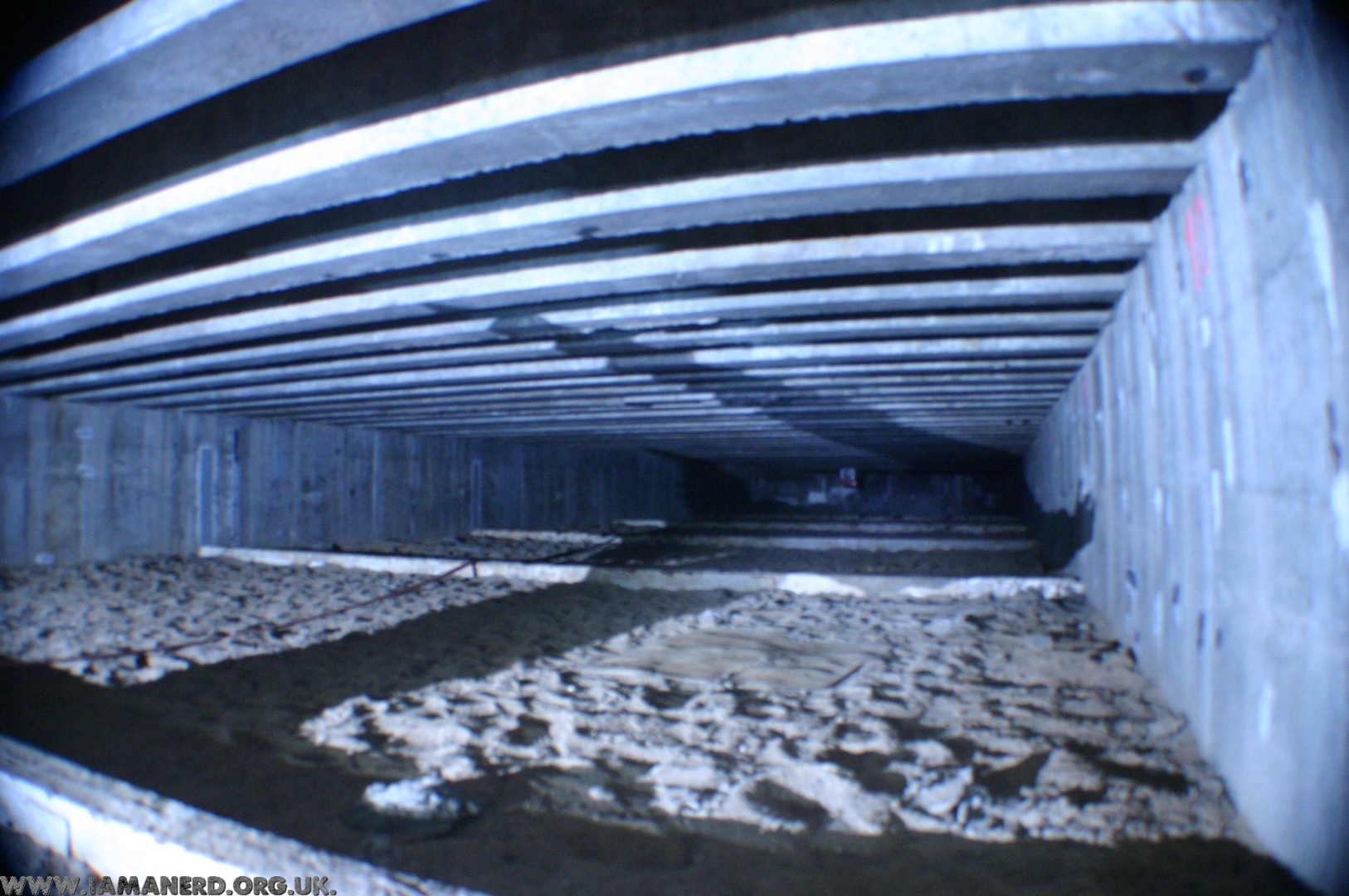
Several of the key area’s within the structure were sprung to absorb shockwaves from a Nuclear attack including security rooms but the main marvel is the 2-storey steel buildings within the bunker, picture in your mind an enormous steel portacabin with offices, medical rooms, communications etc. then imagine there are two of these that are separate to the concrete structure of the bunker with an airgap around them. These buildings within the bunker sat on Giant Nitrogen shock mounts, it is some incredibly impressive engineering.
The beds are hung on springs in an attempt to deal with shockwaves from a nuclear attack.On the left is the steel building within the bunker and you can see the green shock mounts.
Another interesting thing was the ability for us to get inside the blast cap where you could see how it was constructed, the layer of sand, the concrete rood and the air gap to absorb shock.
This rarely seen photo was taken inside the blast cap.
Apparently Honecker only visited the bunker once, he hated it and had no plans to return there.
Norfolk County Hall was built in Norwich in 1966, the lower basement Rooms B38 to B47 housed the County Emergency Headquarters. The Emergency Headquarters consisted of several rooms along one corridor with a blast door at each end.
There was zero information or references online about this Emergency headquarters but based on a hunch I contacted the County Council to enquire about their Cold war Emergency headquarters and its status.
I learned about this protected basement area however I was informed that in 2019 the lower basement was stripped and refurbished with little trace of the HQ remaining, I have since pieced together as much information as possible from the archives and I was also lucky enough to visit what remains.
Drawing based on the “Council Main Emergency Centre Manual” NRO-ACC 2014-247
From at least the 1980’s the basement would have been laid out as above, the various operations rooms were along the left hand side of the corridor with the Communications and briefing rooms on the right with a store and Kitchen. Administration support would have been before the blast door outside of the protected area.
Protective shutters could be fitted over the external windows in the basement rooms that didn’t form part of the protected areas. These rooms could be used as overflow to the main “bunker” or as specified in the civil defense plans.
Much of the equipment in the HQ remained until it was refurbished however its all gone now, including a small BBC radio broadcast desk and RAYNET (Radio Amateurs Emergency Network) station there were also a pair of key switches for controlling the fire alarm sirens. Incidentally, according to a 1994 addendum to the manual, in the event of a “Bomb Alert” the fire alarm bells would sound 2 second blasts for approximately 5 minutes. When deemed safe 2 minutes of short blasts would indicate the “All Clear” condition.
Below are some Archive photos of the External blast protection brackets, broadcast equipment and alarm controls in the rooms from 2015 (No longer present):
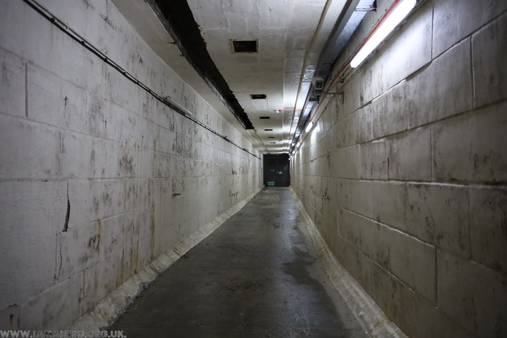
I visited in 2025and although it is now just a corridor you can still see glimpses of its former life.
As you enter what was the Emergency Headquarters you are greeted with the remains of a door frame where the first blast door would have been hung, beyond which is a standard white washed blockwork corridor with several rooms off it. These have all been stripped and renovated (including the kitchen) for use as storage rooms they appear to be the original doors with vents still in place.
At the far end of the corridor to the right is a plant room with air handling unit, filters and a backup generator (All unused).
Finally there is one remaining blast door which leads to the emergency exit, photoluminescent tape is still visible on the vinyl flooring which would have marked the escape route.
The basement rooms are used for storage by the County Council and are not accessible, these photos are from an organised visit in March 2025.
Last year I bought a new fun car, after some back and forth I settled on a 66 Beetle.
This is the third beetle I’ve owned (EER 439D), previously having a 1972 early looker (EJN 484K) with 1600cc Single port engine and a 1977 1200cc (SRT 969R) both of which were my daily drivers and I covered many thousands of miles in them.
My Old Bugs:
This one left the factory in 1965 and is a 1966 1300cc model, it featured in Volksworld in 1994 and had a load of work done to it in 1998, It was “restored” around 2009/2010 and fitted with a large race engine however since then it’s barely covered any miles.
1994 Volksworld and the original restoration:
1998 – 59,998 miles – Receipts from LR super beetles show that it had a lot of work this year. 2010 – 70,337 miles – Fully restored, body off and resprayed as race car with large engine fitted. 2012 – 70,469 miles – MOT Mileage. 2024 – 70,658 miles – When I purchased it!
I bought it with a few issues that needed sorting before it hit the road, the massive engine and rear suspension had been removed prior to my purchase, the supplied axles were wrong and the brakes looked like they came from the bottom of the sea.
I also had some of the scratches touched up and the heating reinstated which had been welded up, I had a 1600 TP engine (originally from a late Mexican Beetle) fitted with twin 34 ICT webbers.
Thanks to DK Autos in biggleswade for getting it back on the road and Julian at parts emporium for supplying many missing items It’s now a lovely car which is fun to drive, has good heating and has a great interior. I’ve already driven more miles in the last few weeks than it has covered in the previous 14 years.
During WW2 this was a Black propaganda site and home to the Aspidistra Radio transmitter. the bunker there was built during WW2 for this purpose.
In the early 1980s the Aspidistra bunker was stripped out and converted into a 3 level deep RGHQ which was subsequently sold to Sussex Police in 1992. They still own the site today and use the site for training.
Below are some photos from an organised visit to the RGHQ in may 2024, the bunker isn’t used these days. It’s interesting as you can see sections where the WW2 and Cold war extensions meet.
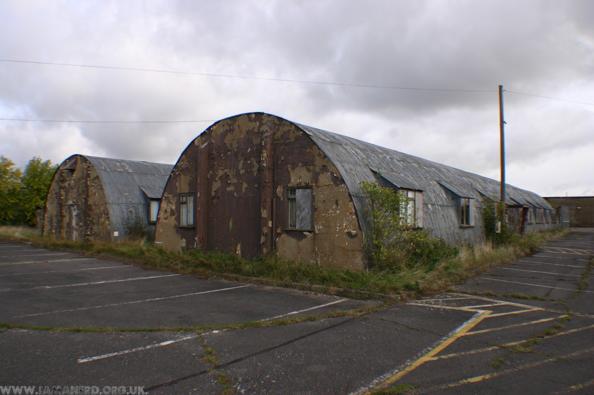
The rest of the site still contains many of the WW2 buildings in various states of repair, Its primary use now as a Police training facility has taken its toll on the buildings and they show the battle scars from many years of Police exercises.
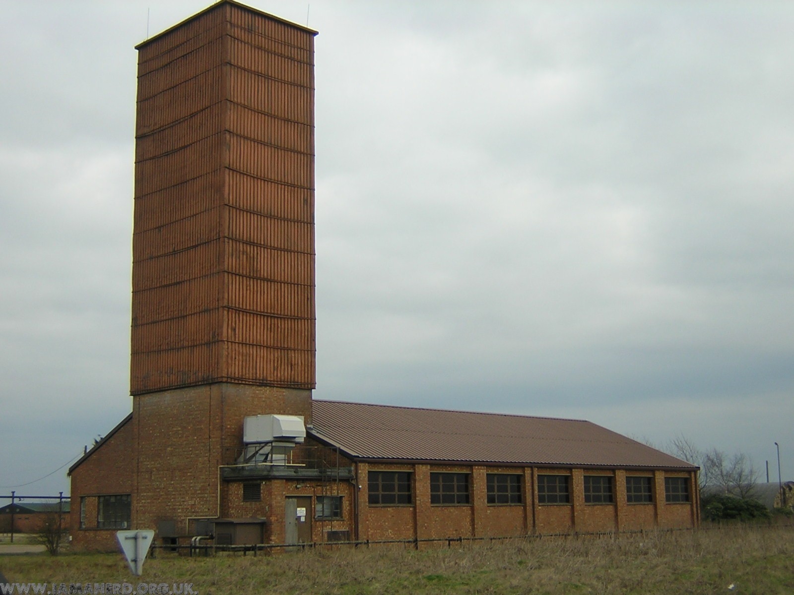
One especially interesting building is the orignal Aspidistra radio broadcasting hall, it was designed by an architect known for his cinema design which can clearly be seen in it.
Alconbury Airfield was originally built in WW2 as an RAF bomber base, the USAF took over in 1942 and In 1995 the Airfield was handed back they do continue to operate from the rest of the site. I’m not going to bother regurgitating the history of Alconbury as it is well documented online already.
In the mid 2000s I worked on the airfield for a company based in Hangar 15 and was I very lucky to visit most of the empty airfield buildings.
Unfortunately I lost most of my photos when a HDD failed on me in 2008 (incidentally this is the reason I love my NAS drive) so many have been lost forever. The few that remain I have posted below, however some are incredibly low resolution.
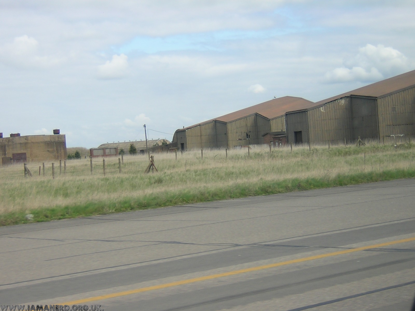
Some General photo’s of the tech site, airfield and buildings 2005-2007:
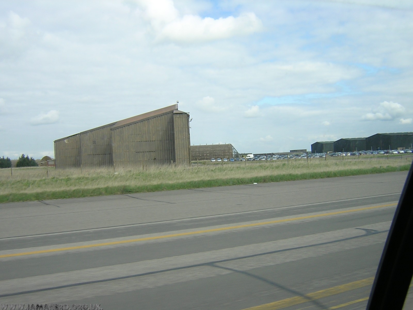
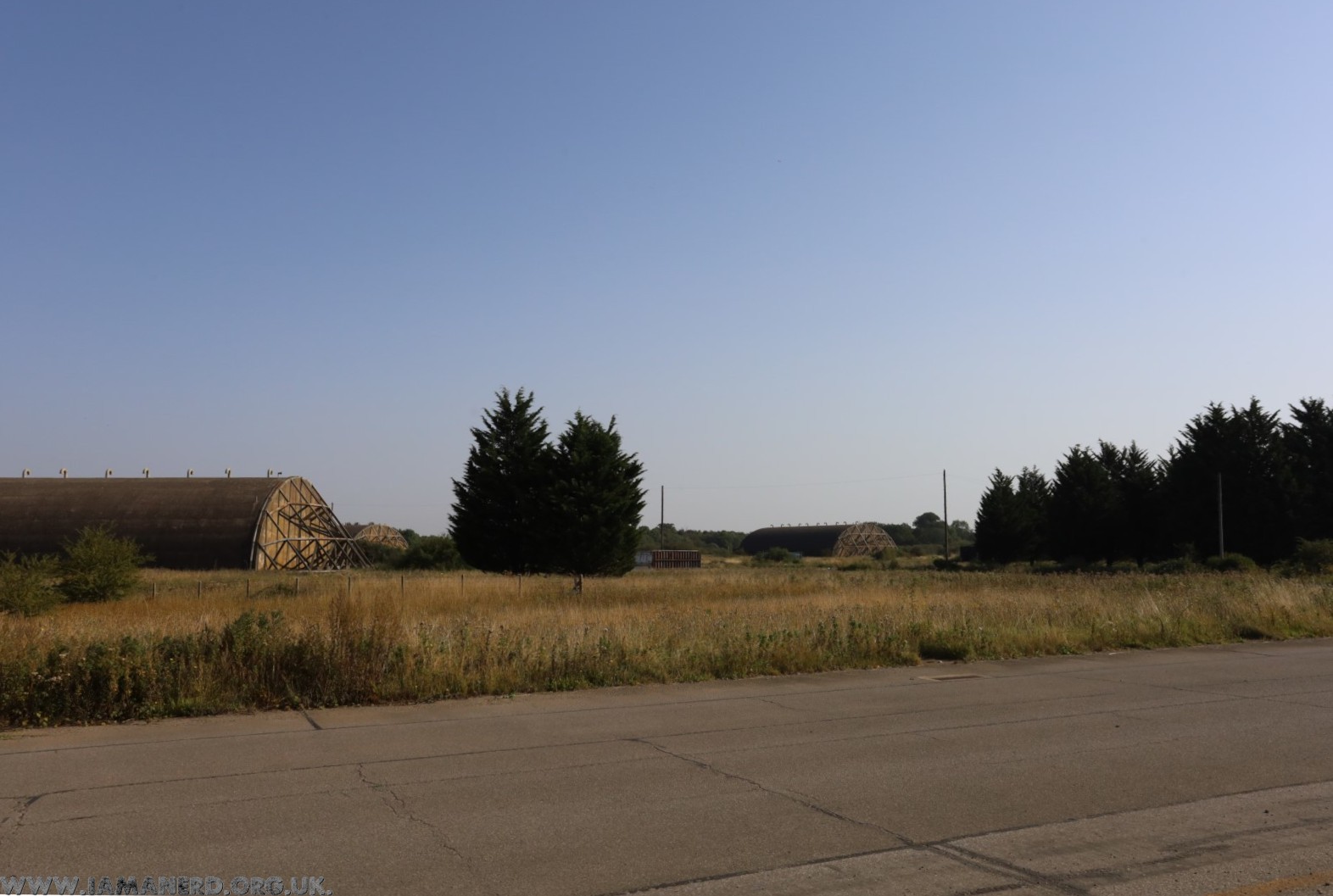
Hardened aircraft shelter (HAS) 3001, The standard HAS on Alconbury are identical to those on all US airfields of the era, There are also some wider HAS built specifically for the TR-1 Spy planes below are a few photos from a standard HAS, building 3001:
On October the 16th 2007 Hanger 4001 which was occupied by Excel logistics at the time Burned to the ground.
Rex Keegan emailed me this at the time “4001 was the first TR-1 Shelter, (called Weather Shelters), constructed and delivered. Prior to these 5 shelters, all TR-1 work was accomplished in Hangar 15 or in part on Hangar 94. These shelters were built to launch aircraft from and had a small back door for the tow vehicle to drive through when towing the aircraft inside, (the TR was towed backwards) and also for the exhaust to pass through when the engine was running. The same concept was used in the hardened shelters for launch. The front door was a bi-forcated overhead contraption with three huge hydraulic pistons. (a maintenance nightmare) The 4 shelters shown were built on the West side of the Old North Runway, near runway side. The 5th shelter was built on the East side of the Old North runway overtop of the old burn pit/dump. 4005 was used as a fuel repair and corrosion control facility, and had an AFFF fire defense system. The four shelters were never used for real world missions. Only training missions were ever flown from them, because Hangar 15 had all the equipment and power necessary for preparing a TR-1 for a particular mission. These continued to be generated and launched from that area until the hardened shelters were able to be utilized. In spite of a lack of facilities and a shortage of equipment, the TR-1 missions flown during their time at Alconbury were deemed highly effective and so technically well advanced over that of our adversaries that their success greatly contributed to ending the cold war.”
Below are some pictures from Hangar 15 when occupied by ELP an Events, TV and Broadcast Lighting company:
Finally for now, here are a few pictures from 2023 of a few of the remaining airfield buildings:
RAF Barnham was home of the 94th Maintenance Unit, this was where the payload of the UKs first Nuclear Deterrent the “Blue Danube” was maintained. The payload had a very short half-life so every few weeks returned here via truck from the southern V-Bomber sites for maintenance.
There was a sister site at RAF Faldingworth that maintained the northern airfields but this is the only complete example remaining more information can be found here https://rafbarnham-nss.weebly.com/
In 2022 with permission from the site owners we took a couple of hundred 360 photos, I’ve used a small selection to create a virtual tour of this amazing location, please enjoy.
A while back I bought this Vox escort lead amplifier, its a 50W model with a blue labelled vox VSL limited speaker and PCB manufactured by the Faraday group of companies.
The PCB says bass 30-50 yet is not a bass amp.
I’m trying to date it and get the Schematic, any information would be greatly recieved!
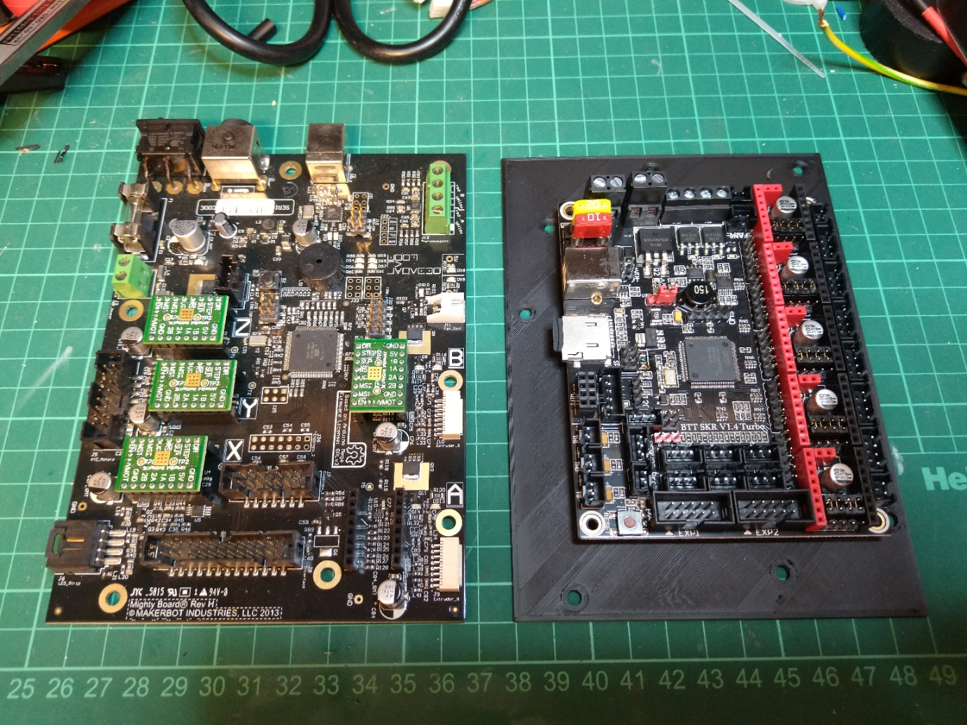
Last year I swapped the original mightyboard and botstep drivers from my replicator 2x over to a modern 32 bit board the bigtreetech SKR 1.4 turbo with 2.4″ TFT and converted it to a bowden setup.
Several people asked how so I’m going to attempt to write it it up. I will continue to add to this as I get time.
This is the basic process you need to follow if you want to do it like I have: – remove mightyboard c/w Botsteps – remove LCD and mount – remove original stepper motor wiring and replaced with generic ones. – cut connectors off the endstops and re-crimp JST connectors on instead. – fit 24vdc PSU under the bed – fit BTT SKR in place of mightyboard with 5 x drivers (I used TMC2208s in standalone mode) – add TFT24 mount and LCD – add extract fan to base – add thermistor to bed in place of the Makerbot one. – cut remaining connectors and changed to JST. – swap the the thermocouples for M3 thermistors (alternatively you can buy a thermocouple board for the SKR) – add mosfet for hotend fan control – edit and compile marlin firmware. Optional steps I undertook: – Converted to Bowden setup by changing the extruders for E3D Titan extruders and the Hotends for an E3D V6 Chimera hotend. – changed the LED strip over to NeoPixel. – made new lid.
JST Connectors and crimping: You will use allot of JST connectors if using the SKR turbo, it is really important that you practice crimping these and ensure you crimp the connectors well, I’m using a cheap ratchet crimper and its pretty rubbish but with practice I’ve managed to crimp the cables pretty well with them.
My conversion process explained: First job is one of the easiest parts of the process, remove all connectors from the the Mightyboard then pull it c/w Botsteps from the standoffs in the base, remove the front door and front panel then remove the LCD and mount.
Now you can remove the original stepper motor looms and replace them with generic ones, I used 4 x 1m and 1 x 0.25M for the Z motor.
At this point you can mount your PSU if you are using an internal one, I chose to screw mine through the base under the bed with 4 X M3 screws.
You can also mount the BTT TFT24 in the printed case now, this screws into the original mounting holes. Be sure to get the EXT connectors and the 5 pin one in the right order, I cut the black wires and crimped a JST connector on the smaller one to ensure that it couldn’t be reversed.
I mounted the BTT main board using standoffs drilled through the bed base but I have subsequently designed an adaptor that you can screw the BTT onto which then clips onto the original standoffs.
Once the new motherboard and TFT is mounted you can finish the wiring, you’ll need to cut the connectors off the Endstops and from the bottom of the extruder/hotend looms.
The Hotend heater cables can be wired directly into the board however the BTT SKR cannot read thermocouples without an additional board so I would swap them for M3 thermistors, you’ll need to crimp JSTs on the thermistor cables (Don’t worry about the polarity).
For the endstops you only need one ground as these are joined on the PCB so just connect the 5v to VCC, Gnd to Gnd and sig to the signal pin.
As the BTT SKR Turbo can only control one fan, I added a Mosfet for the extruder fans (covered in another post here) I also added an extract fan to the base to pull warm air away from the motherboard and PSU paralleled to the output of the mosfet.
I found once completed that the bed thermistor read very low, I think this is because of its placement within the silicone heat mat. I added a new 100K thermistor in the heat bed with a bit of thermal compound and aluminium tape to hold it onto the back of the bed surface, this now reads very accurately.
Firmware: Firstly I am not going to upload my complete firmware as its irrelevant unless you have literally the same setup as me plus If you can’t handle editing code and compiling it you shouldn’t be doing this conversion.
Marlin isn’t complicated and I’m not going into how to compile it but I will help with some useful snippets from mine.
Configuration.h

//Original Hotend Offsets

// Offset of the extruders (uncomment if using more than one and relying on firmware to position when changing).
// The offset has to be X=0, Y=0 for the extruder 0 hotend (default extruder).
// For the other hotends it is their distance from the extruder 0 hotend.
#define HOTEND_OFFSET_X { 0.0, 34.6 } // (mm) relative X-offset for each nozzle
#define HOTEND_OFFSET_Y { 0.0, 0.00 }  // (mm) relative Y-offset for each nozzle
#define HOTEND_OFFSET_Z { 0.0, 0.00 }  // (mm) relative Z-offset for each nozzle

//===========================================================================
//============================== Endstop Settings ===========================
//===========================================================================

// @section homing

// Specify here all the endstop connectors that are connected to any endstop or probe.
// Almost all printers will be using one per axis. Probes will use one or more of the
// extra connectors. Leave undefined any used for non-endstop and non-probe purposes.
//#define USE_XMIN_PLUG
#define USE_YMAX_PLUG
#define USE_ZMIN_PLUG
#define USE_XMAX_PLUG
//#define USE_YMAX_PLUG
//#define USE_ZMAX_PLUG

// Enable pullup for all endstops to prevent a floating state
#define ENDSTOPPULLUPS
#if DISABLED(ENDSTOPPULLUPS)
  // Disable ENDSTOPPULLUPS to set pullups individually
  //#define ENDSTOPPULLUP_XMAX
  //#define ENDSTOPPULLUP_YMAX
  //#define ENDSTOPPULLUP_ZMAX
  //#define ENDSTOPPULLUP_XMIN
  //#define ENDSTOPPULLUP_YMIN
  //#define ENDSTOPPULLUP_ZMIN
  #define ENDSTOPPULLUP_ZMIN_PROBE
#endif

// Enable pulldown for all endstops to prevent a floating state
//#define ENDSTOPPULLDOWNS
#if DISABLED(ENDSTOPPULLDOWNS)
  // Disable ENDSTOPPULLDOWNS to set pulldowns individually
  //#define ENDSTOPPULLDOWN_XMAX
  //#define ENDSTOPPULLDOWN_YMAX
  //#define ENDSTOPPULLDOWN_ZMAX
  //#define ENDSTOPPULLDOWN_XMIN
  //#define ENDSTOPPULLDOWN_YMIN
  //#define ENDSTOPPULLDOWN_ZMIN
  //#define ENDSTOPPULLDOWN_ZMIN_PROBE
#endif

// Mechanical endstop with COM to ground and NC to Signal uses "false" here (most common setup).
#define X_MIN_ENDSTOP_INVERTING true // Set to true to invert the logic of the endstop.
#define Y_MIN_ENDSTOP_INVERTING true // Set to true to invert the logic of the endstop.
#define Z_MIN_ENDSTOP_INVERTING true // Set to true to invert the logic of the endstop.
#define X_MAX_ENDSTOP_INVERTING true // Set to true to invert the logic of the endstop.
#define Y_MAX_ENDSTOP_INVERTING true // Set to true to invert the logic of the endstop.
#define Z_MAX_ENDSTOP_INVERTING true // Set to true to invert the logic of the endstop.
#define Z_MIN_PROBE_ENDSTOP_INVERTING true // Set to true to invert the logic of the probe.

// @section machine

// Invert the stepper direction. Change (or reverse the motor connector) if an axis goes the wrong way.
#define INVERT_X_DIR true
#define INVERT_Y_DIR true
#define INVERT_Z_DIR true

// @section homing

// Direction of endstops when homing; 1=MAX, -1=MIN
// :[-1,1]
#define X_HOME_DIR 1
#define Y_HOME_DIR 1
#define Z_HOME_DIR -1

// @section machine

// The size of the print bed
#define X_BED_SIZE 235
#define Y_BED_SIZE 150

// Travel limits (mm) after homing, corresponding to endstop positions.
#define X_MIN_POS 0
#define Y_MIN_POS 0
#define Z_MIN_POS 0
#define X_MAX_POS 235
#define Y_MAX_POS 150
#define Z_MAX_POS 150
Configuration_adv.h

#define E0_AUTO_FAN_PIN P1_00
That is kind of it for the basics, I’ll try to add any more information as I think of it but there should be enough here to get you through a conversion, I’ll try and write up my bowden conversion soon.
To provide the best experiences, we use technologies like cookies to store and/or access device information. Consenting to these technologies will allow us to process data such as browsing behavior or unique IDs on this site. Not consenting or withdrawing consent, may adversely affect certain features and functions.
Functional
Always active
The technical storage or access is strictly necessary for the legitimate purpose of enabling the use of a specific service explicitly requested by the subscriber or user, or for the sole purpose of carrying out the transmission of a communication over an electronic communications network.
Preferences
The technical storage or access is necessary for the legitimate purpose of storing preferences that are not requested by the subscriber or user.
Statistics
The technical storage or access that is used exclusively for statistical purposes.The technical storage or access that is used exclusively for anonymous statistical purposes. Without a subpoena, voluntary compliance on the part of your Internet Service Provider, or additional records from a third party, information stored or retrieved for this purpose alone cannot usually be used to identify you.
Marketing
The technical storage or access is required to create user profiles to send advertising, or to track the user on a website or across several websites for similar marketing purposes.