A while back I bought this Vox escort lead amplifier, its a 50W model with a blue labelled vox VSL limited speaker and PCB manufactured by the Faraday group of companies.
The PCB says bass 30-50 yet is not a bass amp.
I’m trying to date it and get the Schematic, any information would be greatly recieved!
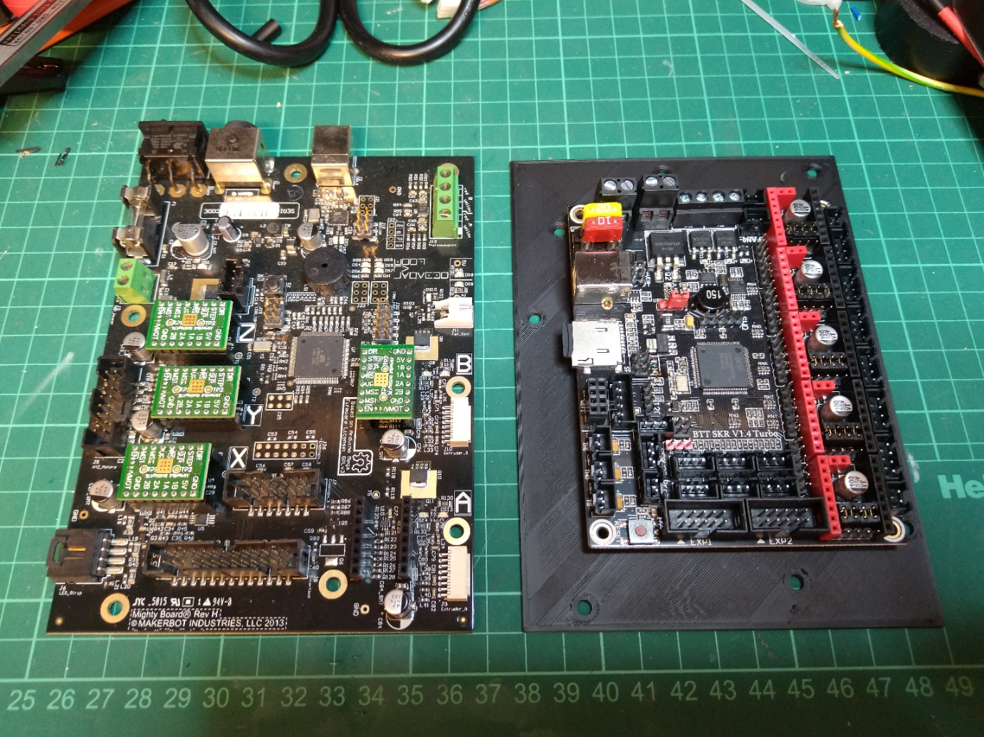
Last year I swapped the original mightyboard and botstep drivers from my replicator 2x over to a modern 32 bit board the bigtreetech SKR 1.4 turbo with 2.4″ TFT and converted it to a bowden setup.
Several people asked how so I’m going to attempt to write it it up. I will continue to add to this as I get time.
This is the basic process you need to follow if you want to do it like I have: – remove mightyboard c/w Botsteps – remove LCD and mount – remove original stepper motor wiring and replaced with generic ones. – cut connectors off the endstops and re-crimp JST connectors on instead. – fit 24vdc PSU under the bed – fit BTT SKR in place of mightyboard with 5 x drivers (I used TMC2208s in standalone mode) – add TFT24 mount and LCD – add extract fan to base – add thermistor to bed in place of the Makerbot one. – cut remaining connectors and changed to JST. – swap the the thermocouples for M3 thermistors (alternatively you can buy a thermocouple board for the SKR) – add mosfet for hotend fan control – edit and compile marlin firmware. Optional steps I undertook: – Converted to Bowden setup by changing the extruders for E3D Titan extruders and the Hotends for an E3D V6 Chimera hotend. – changed the LED strip over to NeoPixel. – made new lid.
JST Connectors and crimping: You will use allot of JST connectors if using the SKR turbo, it is really important that you practice crimping these and ensure you crimp the connectors well, I’m using a cheap ratchet crimper and its pretty rubbish but with practice I’ve managed to crimp the cables pretty well with them.
My conversion process explained: First job is one of the easiest parts of the process, remove all connectors from the the Mightyboard then pull it c/w Botsteps from the standoffs in the base, remove the front door and front panel then remove the LCD and mount.
Now you can remove the original stepper motor looms and replace them with generic ones, I used 4 x 1m and 1 x 0.25M for the Z motor.
At this point you can mount your PSU if you are using an internal one, I chose to screw mine through the base under the bed with 4 X M3 screws.
You can also mount the BTT TFT24 in the printed case now, this screws into the original mounting holes. Be sure to get the EXT connectors and the 5 pin one in the right order, I cut the black wires and crimped a JST connector on the smaller one to ensure that it couldn’t be reversed.
I mounted the BTT main board using standoffs drilled through the bed base but I have subsequently designed an adaptor that you can screw the BTT onto which then clips onto the original standoffs.
Once the new motherboard and TFT is mounted you can finish the wiring, you’ll need to cut the connectors off the Endstops and from the bottom of the extruder/hotend looms.
The Hotend heater cables can be wired directly into the board however the BTT SKR cannot read thermocouples without an additional board so I would swap them for M3 thermistors, you’ll need to crimp JSTs on the thermistor cables (Don’t worry about the polarity).
For the endstops you only need one ground as these are joined on the PCB so just connect the 5v to VCC, Gnd to Gnd and sig to the signal pin.
As the BTT SKR Turbo can only control one fan, I added a Mosfet for the extruder fans (covered in another post here) I also added an extract fan to the base to pull warm air away from the motherboard and PSU paralleled to the output of the mosfet.
I found once completed that the bed thermistor read very low, I think this is because of its placement within the silicone heat mat. I added a new 100K thermistor in the heat bed with a bit of thermal compound and aluminium tape to hold it onto the back of the bed surface, this now reads very accurately.
Firmware: Firstly I am not going to upload my complete firmware as its irrelevant unless you have literally the same setup as me plus If you can’t handle editing code and compiling it you shouldn’t be doing this conversion.
Marlin isn’t complicated and I’m not going into how to compile it but I will help with some useful snippets from mine.
Configuration.h

//Original Hotend Offsets

// Offset of the extruders (uncomment if using more than one and relying on firmware to position when changing).
// The offset has to be X=0, Y=0 for the extruder 0 hotend (default extruder).
// For the other hotends it is their distance from the extruder 0 hotend.
#define HOTEND_OFFSET_X { 0.0, 34.6 } // (mm) relative X-offset for each nozzle
#define HOTEND_OFFSET_Y { 0.0, 0.00 }  // (mm) relative Y-offset for each nozzle
#define HOTEND_OFFSET_Z { 0.0, 0.00 }  // (mm) relative Z-offset for each nozzle

//===========================================================================
//============================== Endstop Settings ===========================
//===========================================================================

// @section homing

// Specify here all the endstop connectors that are connected to any endstop or probe.
// Almost all printers will be using one per axis. Probes will use one or more of the
// extra connectors. Leave undefined any used for non-endstop and non-probe purposes.
//#define USE_XMIN_PLUG
#define USE_YMAX_PLUG
#define USE_ZMIN_PLUG
#define USE_XMAX_PLUG
//#define USE_YMAX_PLUG
//#define USE_ZMAX_PLUG

// Enable pullup for all endstops to prevent a floating state
#define ENDSTOPPULLUPS
#if DISABLED(ENDSTOPPULLUPS)
  // Disable ENDSTOPPULLUPS to set pullups individually
  //#define ENDSTOPPULLUP_XMAX
  //#define ENDSTOPPULLUP_YMAX
  //#define ENDSTOPPULLUP_ZMAX
  //#define ENDSTOPPULLUP_XMIN
  //#define ENDSTOPPULLUP_YMIN
  //#define ENDSTOPPULLUP_ZMIN
  #define ENDSTOPPULLUP_ZMIN_PROBE
#endif

// Enable pulldown for all endstops to prevent a floating state
//#define ENDSTOPPULLDOWNS
#if DISABLED(ENDSTOPPULLDOWNS)
  // Disable ENDSTOPPULLDOWNS to set pulldowns individually
  //#define ENDSTOPPULLDOWN_XMAX
  //#define ENDSTOPPULLDOWN_YMAX
  //#define ENDSTOPPULLDOWN_ZMAX
  //#define ENDSTOPPULLDOWN_XMIN
  //#define ENDSTOPPULLDOWN_YMIN
  //#define ENDSTOPPULLDOWN_ZMIN
  //#define ENDSTOPPULLDOWN_ZMIN_PROBE
#endif

// Mechanical endstop with COM to ground and NC to Signal uses "false" here (most common setup).
#define X_MIN_ENDSTOP_INVERTING true // Set to true to invert the logic of the endstop.
#define Y_MIN_ENDSTOP_INVERTING true // Set to true to invert the logic of the endstop.
#define Z_MIN_ENDSTOP_INVERTING true // Set to true to invert the logic of the endstop.
#define X_MAX_ENDSTOP_INVERTING true // Set to true to invert the logic of the endstop.
#define Y_MAX_ENDSTOP_INVERTING true // Set to true to invert the logic of the endstop.
#define Z_MAX_ENDSTOP_INVERTING true // Set to true to invert the logic of the endstop.
#define Z_MIN_PROBE_ENDSTOP_INVERTING true // Set to true to invert the logic of the probe.

// @section machine

// Invert the stepper direction. Change (or reverse the motor connector) if an axis goes the wrong way.
#define INVERT_X_DIR true
#define INVERT_Y_DIR true
#define INVERT_Z_DIR true

// @section homing

// Direction of endstops when homing; 1=MAX, -1=MIN
// :[-1,1]
#define X_HOME_DIR 1
#define Y_HOME_DIR 1
#define Z_HOME_DIR -1

// @section machine

// The size of the print bed
#define X_BED_SIZE 235
#define Y_BED_SIZE 150

// Travel limits (mm) after homing, corresponding to endstop positions.
#define X_MIN_POS 0
#define Y_MIN_POS 0
#define Z_MIN_POS 0
#define X_MAX_POS 235
#define Y_MAX_POS 150
#define Z_MAX_POS 150
Configuration_adv.h

#define E0_AUTO_FAN_PIN P1_00
That is kind of it for the basics, I’ll try to add any more information as I think of it but there should be enough here to get you through a conversion, I’ll try and write up my bowden conversion soon.
When I built my Replicator 2X using a BTT SKR 1.4 Turbo I was disappointed to learn that only one of the three fans is controllable.
Makerbot Replicator 2X with BTT SKR
I really wanted an automatic extruder fan and with an external MOSFET it’s a really simple thing to setup.
DF Robot MOSFET
All you need to do is connect a MOSFET to a spare pin (I chose the power detect plug).
Using a DFRobot GRAVITY MOSFET (other brands are available) I connected the red to 5v, black to GND and green to pin 1.00
Pwr Detect plug
I connected the fan to the output of the mosfet using the output from fan1 for the VIN but you could obviously use your PSU aswell (Make sure this is the correct voltage for the fan!!)
In configuration.adv I changed the extruder fan pin to “P1_00” from “-1” compiled Marlin, uploaded it and bingo!
After successfully running for 18 months my SD card failed probably due to the amount of mysql data read/writes. Luckily it failed read only so I didn’t loose too much data however I decided to start fresh using rasbian stretch and an external mysql table on a traditional drive (Not an SD Card) so here is a little guide of what I did again it assumes you have no mouse, keyboard or monitor attached and is correct as of December 2017
Prepare the Pi:
1. Download the latest Raspbean Stretch Image and Using your favourite method, prepare your SD card using the downloaded image for the Pi (I used Etcher on my laptop).
2. Add an empty file to the boot folder called “SSH”
3. Plug an ethernet cable into the Pi and connect to a router serving DHCP and Boot your Pi using the newly prepared SD card.
4. Using a network scanner (or login to your router) to determine the IP address of your Pi, I use fing on my smartphone.
5. Log into the pi using SSH in OSX type
SSH pi@IP Address
and use the password “raspberry”
6. type
sudo raspi-config
Change User Password – Follow Prompts to set a new password
Localisation Options – set your timezone and wifi country which will be assigned depending on the IP address jiofi.local.html service provides you.
Interfacing options > Serial – Turn OFF serial prompt but turn ON Serial Hardware
Interfacing options > VNC – Disable VNC Server as using tightVNC
Exit raspi-config and reboot when prompted.
sudo apt-get update sudo apt-get upgrade -y
Configure VNC:
1. to Install VNC Viewer type
sudo apt-get install tightvncserver
2. If you want to change the VNC port type
sudo nano /usr/bin/vncserver
find the line
$vncPort = 5900 + $displayNumber;
and change 5900 to the port you want to use, I use 59000 which equated to 59001 in real life. Press Ctrl>X, Y, Enter to save and exit nano
3. To make VNC run from boot you need to create a script, type
save and exit nano, reboot and VNC should now run from startup!
4. You can now connect to your Pi using VNC! so VNC into your Pi and set a static IP using the network settings GUI in the top right of the screen and reboot, the next few steps can be done through SSH or terminal in VNC its up to you.
Configure Webserver and PhpMyadmin:
As I am initially only using the RPi to collect sensor data and write it to an external mysql table and web server I have skipped this step but left its heading in.
I used my Synology NAS and installed MariaDB and web station (Apache)
Setup Shares:
1. we are going to setup samba shares to make moving scripts etc easier, so install samba
sudo apt-get install samba samba-common-bin -y
2. once installed type
sudo nano /etc/samba/smb.conf
scroll down and make sure you have the correct workgroup (I just use WORKGROUP) and that Wins Support is enabled.
3. to be safe you should only add your pi user so type
smbpasswd -a
and enter your desired password, if you do want to add the root user type
5. You should now be able to connect to these shares using standard UNC paths from your windows or macintosh computers
Setup the “Slice of Radio” (Wireless message bridge)
Because of a change to the way the Pi 3 uses Uart, we need a workaround to get the Slice of radio working.
1. type
sudo nano /boot/config.txt
and add
# Change device tree to enable slice of radio

dtoverlay=pi3-miniuart-bt
to the end of the file then reboot
sudo reboot
If you haven’t installed your slice of radio yet, shut down your Pi and fit it
sudo shutdown 0 otherwise reboot the Pi sudo reboot
3. next we need to setup your radios, If you’ve already done this skip to step 5 otherwise dowload launchpad from github and copy it to your pi, this is a collection of gui python scripts used to configure your wireless sensors. I have put mine in home/pi/launchpad using vnc in terminal run
gksudo python LaunchPad.py
to fire it up. (using gksudo rather than sudo fixes display 0.0 errors caused by running X programs on VNC, you may not need this if using a monitor.)
4. In LaunchPad, Click on message bridge and hit start wait a minute, then click on Configuration wizard (If this is a rebuild rather than fresh install you can skip configuration and just install minicom to check the sensors are responding)then select “serial” in the next window you can configure your sensors, press the configure button on a sensor for one second, wait for it to communicate with wireless bridge and follow the on screen setup, repeat for each sensor. Once you are finished exit LaunchPad
5. next we install minicom to test communication with your sensors is working correctly so type
sudo apt-get install minicom -y
once installed we need to run
minicom -b 9600 -o -D /dev/ttyAMA0
This will open minicom and if all is well you will see your sensors responding, remember they will only report as often as you have told them to so you may need to be patient! Exit minicom when you are happy that the sensors are responding.
Ctrl A, X
BACKUP your SD Card:
At this point I’d recommend backing up your SD card image and archiving it, also I would suggest a Cron job to backup any scripts you write to an external destination.
Summary
That is kind of it for configuration, you now have a Pi 3 running the latest Raspbian, you have sensors attached and reporting,.
Originally I followed this project to get me going http://www.lourenco.eu/temperature/instructions.html but I have since ditched it in place of my own version.
I recently discovered the Synology community which contains some excellent packages to enhance the capability of a Synology NAS however although listed the “beets” package doesn’t appear on my DS215j so after doing some digging and figuring out an easy way to install it I thought I’d share that knowledge.
I take no responsibility for damage to your system I am just sharing what I have learned.
First using package centre ensure python is installed on your NAS (I am using “python” from the community repo but “python3” should work aswell) and that telnet (not recommended) or SSH access is enabled.
Once this is done you can install beets by typing sudo pip install beets then install requests (for fetchart to work) by typing sudo pip install requests
beets is now installed, to check its working type beet version this will return the beets and python version numbers and any active plugins (There won’t be any yet!)
Next we need to edit the beets config type beet config -p this will tell you the location of the config file you’ll need to copy this and edit it off the synology to edit it.
type cp /var/services/homes/admin/.config/beets/config.yaml /volume1/music/config.yaml to copy the blank file into the music folder, using my PC I edited the file to contain this: (You will need to edit this to reflect your folder structure and where you want the files to live!)
Once edited save the file on the NAS in “music” and run the following cp /volume1/music/config.yaml /var/services/homes/admin/.config/beets/config.yaml this will overwrite the blank config file with the one in “music”.
You can now import your files, I have around 100GB of music in /volume1/music/old so I ran beet import /volume1/music/old -qg this automatic import took a long time (Several hours) and imported around 45GB of files, running beet import /volume1/music/old -qg imported another 10GB relatively quickly (A couple of hours)
Unfortunately once the Autotagging has run you’ll need to do a manual import and search to import the rest of the files using the command beet import /volume1/music/old once this starts you will be prompted to import media, unfortunately this process in laborious but its the price you’ll pay for an organised media collection. The one really useful feature missing from beets would be for an option to automatically skip duplicates but prompt for everything else!
After all the issues migrating Wheezy over I decided to start from scratch with the Pi 3 and my wirelessthings sensors. This guide is pretty poorly written but is step by step everything I did. it assumes you have no mouse, keyboard or monitor attached.
This post is correct as of the 9th of april 2016
Prepare the Pi:
1. Download the latest Raspbean Jessie Image and Using your favourite method, prepare your SD card using the downloaded image for the Pi (I used Apple Pi Baker other GUIs are available).
2. Plug an ethernet cable into the Pi and connect to a router serving DHCP and Boot your Pi using the newly prepared SD card.
3. Using a network scanner (or login to your router) to determine the IP address of your Pi, I use fing on my smartphone.
4. Log into the pi using SSH in OSX type
SSH pi@IP Address
and use the password “raspberry”
5. type
sudo raspi-config
select Internationalisation Options and set your timezone then go into Advanced options and turn ON serial! Exit raspi-config and reboot your Pi when prompted
It is good practice to expand your filesystem at this point however I haven’t found raspi-config GUI very good at this so run:
raspi-config --expand-rootfs and reboot when finished
6. SSH back into your pi run:
sudo apt-get update sudo apt-get upgrade -y
7. Change the default password! type
passwd
and enter your old password followed by your new one as prompted!
Configure VNC:
1. to Install VNC Viewer type
sudo apt-get install tightvncserver
2. If you want to change the VNC port type
sudo nano /usr/bin/vncserver
find the line
$vncPort = 5900 + $displayNumber;
and change 5900 to the port you want to use, I use 59000 which equated to 59001 in real life. Press Ctrl>X, Y, Enter to save and exit nano
3. To make VNC run from boot you need to create a script, type
save and exit nano, reboot and VNC should now run from startup!
4. You can now connect to your Pi using VNC! so VNC into your Pi and set a static IP using the network settings GUI in the top right of the screen and reboot, the next few steps can be done through SSH or terminal in VNC its up to you.
If you haven’t installed your slice of radio yet, shut down your Pi and fit it
sudo shutdown 0 otherwise reboot the Pi sudo reboot
3. next we need to setup your radios, If you’ve already done this skip to step 5 otherwise dowload launchpad from wirelessthings and copy it to your pi, this is a collection of gui python scripts used to configure your wireless sensors. I have put mine in home/pi/launchpad using vnc in terminal run
gksudo python LaunchPad.py
to fire it up. (using gksudo rather than sudo fixes display 0.0 errors caused by running X programs on VNC, you may not need this if using a monitor.)
4. In LaunchPad, Click on message bridge and hit start wait a second, then click on Configuration wizard (ignore the message stating “Message bridge not found”) then select “serial” in the next window you can configure your sensors, press the configure button on a sensor for one second, wait for it to communicate with wireless bridge and follow the on screen setup, repeat for each sensor. Once you are finished exit LaunchPad
5. next we install minicom to test communication with your sensors is working correctly so type
sudo apt-get install minicom -y
once installed we need to run
minicom -b 9600 -o -D /dev/ttyAMA0
This will open minicom and if all is well you will see your sensors responding, remember they will only report as often as you have told them to so you may need to be patient! Exit minicom when you are happy that the sensors are responding.
Ctrl A, X
BACKUP your SD Card:
At this point I’d recommend backing up your SD card image and archiving it:
Apache2 optimisation:
you can disable unused modules to speed up apache2, I disabled these but it’s made no difference.
Thats kind of it for configuration, you now have a Pi 3 running the latest Raspbian, you have sensors attached and reporting, you have a webserver installed, mysql, php and python so you can do with it what you like!
Originally I followed this project to get me going http://www.lourenco.eu/temperature/instructions.html but I have since ditched it in place of my own version.
I wanted to add hot water temperature to my raspberry pi powered “Pimometer” but wirelessthings dont make a suitable XRF sensor.
I decided to buy a standard wirelessthings temperature sensor, unsoldered the thermistor and added a flying lead resoldering the thermistor to this, making sure to insulate the legs of the thermistor.
Luckily (or not) our hot water cylinder has no insulation around the immersion heater at the top of the tank, using some thermal paste i attached it to the bare metal and taped it in place with some foil tape. I then added it to my pi and left it to get some readings.
The final step was making sure the readings are relatively accurate, using a thermometer under the hot water I compared the real life temperature to the readings on the pi and to my surprise they are are only a couple of degrees out so definitely accurate enough for what I need.
After seven days of data logging I lagged the hot water cylinder to see if there was any significant improvement in heat retention.
NOTE: When first testing this setup I didn’t use thermal paste, the readings were around 30% out which was nowhere near accurate enough, by adding the thermal paste and angling the bead of the thermistor it has improved this considerably.
This is not an exhaustive tutorial but it should explain roughly how I interfaced some “wirelessthings” wireless XRF temperature sensors and a “slice of radio” to my Raspberry Pi and logged data from them.
I will eventually get round to writing it properly.
To begin with I downloaded the lastest Raspian Wheezy, I know there are newer distributions available but I would stick with wheezy as they have changed the way to access the serial port.
Using Apple Pi Baker (a GUI SD card preparation application) I made the SD card ready for my Pi, put it in the Pi and booted with an ethernet cable plugged into my router.
SSH is installed by default on wheezy so I used fing to determine the Pi’s address on my network then used SSH with the user “pi” and password “raspberry”
I then updated the system and changed my password: Sudo apt-get update
Sudo apt-get upgrade
And installed VNC Server, The instructions here https://www.raspberrypi.org/documentation/remote-access/vnc/ explain how to setup and install Tight VNC Server
Finally you need to get the sensors logging I approximately followed the instructions here http://www.lourenco.eu/temperature/instructions.html just editing the python script to accept the message format of the wirelessthings sensors.
btw you can make your script executable using chmod +x monitor.py and in the VNC instructions above it shows how to get a script to run at startup.
In theory your sensor data should now be appearing in the SQLITE DB from boot.
What you do with it all is now down to you, you can use SQL Lite Database Browser for GUI access to your DB, I installed apache2 with php and wrote a very simple page to pull data from the SQL.
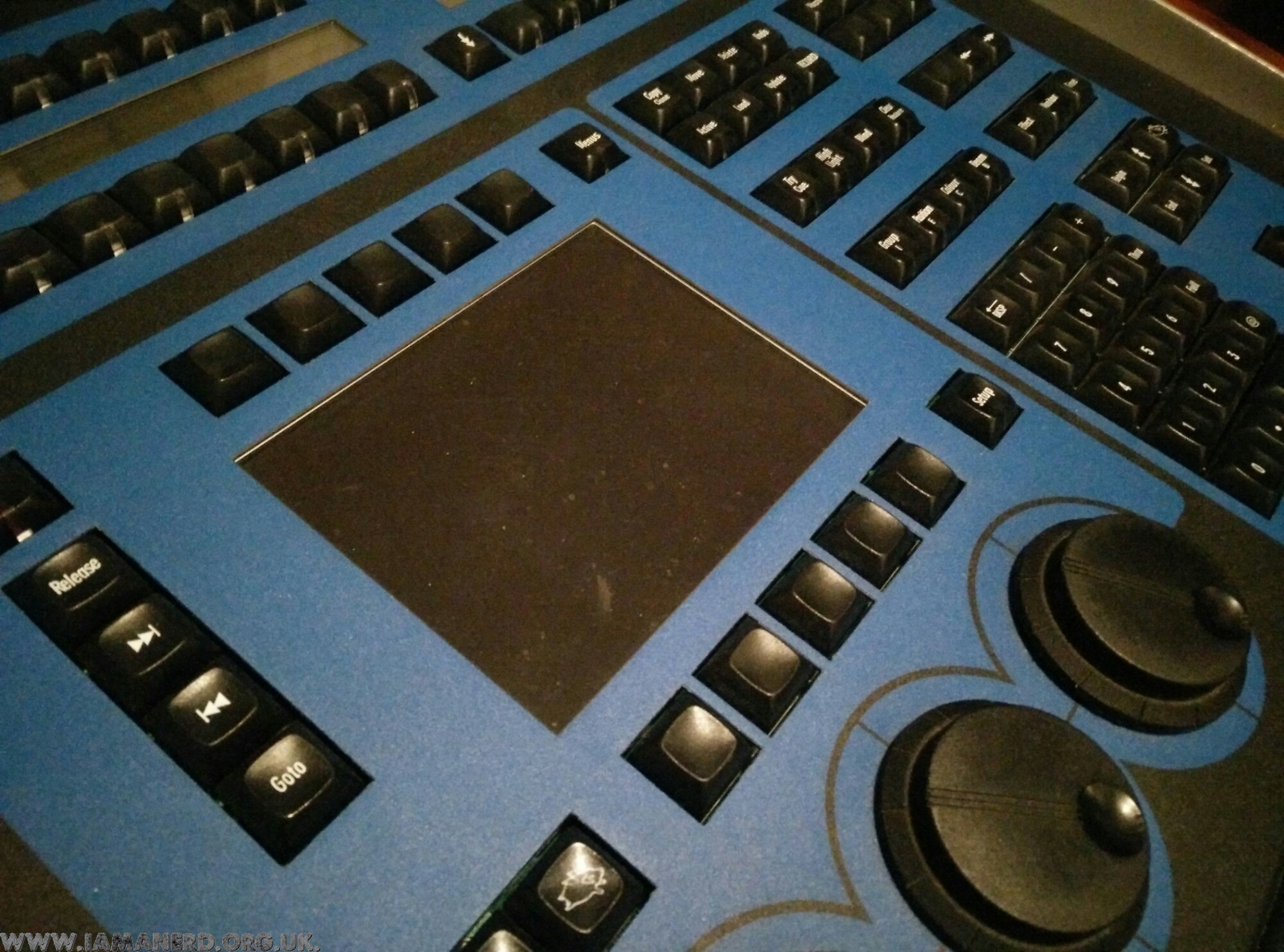
The backlight on my Hog 1000 died, this is not surprising considering its age and the fact that backlights do eventually die! Sadly the inverter and cold cathode tube for this console are no longer available so I decided to replace it with some LED strip!
I first removed the main PCB then the LCD, I de-soldered the inverter and took the cold cathode tube out of the casing.
I removed the foil that covered the tube and slid a strip of daylight LED tape into the aluminum holder (covering the terminals on the tape and the cable where it exits) with some PVC tape.
Finally I found a12vdc supply from the rear PCB and I put the console back together!
It works a treat and is very bright, you can’t control how bright it is from the console anymore and it doesn’t automatically switch off when the console is inactive but beggars cannot be choosers and it works brilliantly!
To get around the dimming issue I have ordered a 12v LED dimmer switch online and plan to fit it just under one of the wooden side panels. I did consider taking a feed from the other LCD backlights so that they dimmed and turned off together in the end I decided it was safer to leave them as they were and not fiddle too much!
Its called “Like Harvesting” and its a way for people or organisations to boost their facebook pages allowing them to target larger audiences with subsequent adverts or to sell likes and potentially your profile information to third parties.
Usually these will be a picture, maybe a small girl with a sign saying things such as “my mum says if I get 200,000 likes then I can get a pony”, a picture of a sports car/iPad/high value item with a bow on it pretending to be a competition or more often than not a high value voucher offer for a supermarket or similar.
Its not going to hurt you but think before you share anything on Facebook, try and make sure posts are not created purely for likes and check out the person posting it to see if their page looks legit.
Finally, if the offer seems too good to be true then it probably is!
Manage Consent
To provide the best experiences, we use technologies like cookies to store and/or access device information. Consenting to these technologies will allow us to process data such as browsing behavior or unique IDs on this site. Not consenting or withdrawing consent, may adversely affect certain features and functions.
Functional
Always active
The technical storage or access is strictly necessary for the legitimate purpose of enabling the use of a specific service explicitly requested by the subscriber or user, or for the sole purpose of carrying out the transmission of a communication over an electronic communications network.
Preferences
The technical storage or access is necessary for the legitimate purpose of storing preferences that are not requested by the subscriber or user.
Statistics
The technical storage or access that is used exclusively for statistical purposes.The technical storage or access that is used exclusively for anonymous statistical purposes. Without a subpoena, voluntary compliance on the part of your Internet Service Provider, or additional records from a third party, information stored or retrieved for this purpose alone cannot usually be used to identify you.
Marketing
The technical storage or access is required to create user profiles to send advertising, or to track the user on a website or across several websites for similar marketing purposes.